Shape meter
Meter=Shape is used to create one or more vector graphic shapes.
Quick Jump
Overview
The meter will consist of one or more Shape...Shape2...ShapeN objects.
You first define the type of Shape, the relative starting position in the meter, and required and optional shape definition parameters.
[MeterShape] |
In this example we are saying "Create a rectangle, starting at an X of 0 and a Y of 0 relative to the meter, with a width of 100, and a height of 50." This is the most basic example of the meter, and will create a 100 X 50 rectangle with a default white fill color and a default 1 pixel black drawing stroke.
You can then add Attribute and Transform modifiers to each shape, which can control things like Fill Color, StrokeWidth, Rotate, Scale, and much more.
[MeterShape] |
Modifiers are added on the ShapeN option by defining them separated by the pipe | character. All modifiers are optional, and they can be in any order in the option, after the shape definition. This example adds "Use a solid black fill color in the shape, change the width of the drawing stroke to 4 pixels, and color the stroke white."
Shapes in a meter can also be Combined, which will allow you to merge two or more separate shapes in a variety of ways.
[MeterShapes] |
If you have more than one shape defined in the meter, you may want them to share some or all modifiers, rather than repeating them in each ShapeN option. This is done with the Extend modifier. The way this works is that you use the keyword Extend, followed by one or more named identifiers. Then you add that named identifier as a separate option on the meter, and in it put any modifiers you want to share.
[MeterShapes] |
Note: The EndX and EndY parameters in the Line shape, as well as in the Arc and Curve shapes, and the LineTo, ArcTo, CurveTo parameters in the Path shape, are not inclusive. The line is drawn up to the points defined by EndX and EndY. A line drawn from pixel 0 to pixel 100 will be drawn on pixels 0 through 99, and be 100 pixels in length.
Options
- General meter options
-
All general meter options are valid.
Shape, Shape2, Shape3...-
This is the only Shape meter specific option used. It will define the Shape Type and its definition parameters, and any Attribute and Transform modifiers for the shape(s) to be drawn.
There can be from one to a reasonably unlimited number of shapes in a single Shape meter. Multiple shapes are drawn in the numerical order of the ShapeN, so in the case of overlap, higher numbered shapes will be drawn on top / in front of lower numbered shapes.
[MeterShapes]
Meter=Shape
Shape=Rectangle 25,25,100,100 | Fill Color 106,159,212,255 | Rotate 45
Shape2=Rectangle 50,50,50,50,25 | Fill Color 255,255,255,255 | StrokeWidth 4
Shape Types
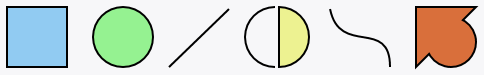
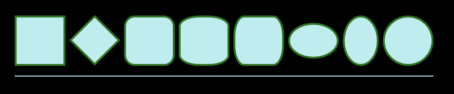
RectangleParameters:X, Y, Width, Height, RadiusX, RadiusY-
A closed rectangle or rounded rectangle.
Parameters:
X(required): X coordinate of the shape relative to the meter.Y(required): Y coordinate of the shape relative to the meter.Width(required): Width of the shape.Height(required): Height of the shape.RadiusX(optional): Radius of the corners of rounded rectangles. If used with the optional ' RadiusY', this will represent the radius on the X-axis.RadiusY(optional): Y-Axis radius of the corners of rounded rectangles.
Examples:
Shape=Rectangle 0,0,100,50
Shape=Rectangle 0,0,100,50,10
Shape=Rectangle 0,0,100,50,20,5 EllipseParameters:CenterX, CenterY, RadiusX, RadiusY-
A closed circle or oval.
Parameters:
CenterX(required): X coordinate of the center of the ellipse.CenterY(required): Y coordinate of the center of the ellipse.RadiusX(required): Radius of the ellipse. If used with the optional 'RadiusY', this will represent the radius on the X-axis.RadiusY(optional): Radius of the ellipse on the Y-axis.
Examples:
Shape=Ellipse 50,50,50
Shape=Ellipse 50,50,50,25Note on Ellipse:
The shape is drawn centered on the position defined by CenterX and CenterY. In a sense, it draws from the center out. Be sure that CenterX and CenterY, or the X and Y on the meter, leave enough room in the overall skin to not truncate the shape at the left and top. LineParameters:StartX, StartY, EndX, EndY-
An open line between two points.
Parameters:
StartX(required): X coordinate of the starting point of the line.StartY(required): Y coordinate of the starting point of the line.EndX(required): X coordinate of the ending point of the line.EndY(required): Y coordinate of the ending point of the line.
Example:
Shape=Line 50,50,200,200
ArcParameters: (See below)-
An open arc between two points.
See our live interactive arc example.Parameters:
StartX(required): X coordinate of the starting point of the arc.StartY(required): Y coordinate of the starting point of the arc.EndX(required): X coordinate of the ending point of the arc.EndY(required): Y coordinate of the ending point of the arc.RadiusX(optional): X radius of the arc.RadiusY(optional): Y radius of the arc.RotationAngle(optional): Positive or negative angle of rotation. (see note)SweepDirection(optional): Clockwise (0 - default) or counter-clockwise (1) direction.ArcSize(optional): Use small (0 - default) or large (1) arc size. (see note)ShapeEnding(optional): Leave the shape open (0 - default) or automatically close (1) the shape.
The first 4 parameters are required. The rest are optional, but in order. When you use an optional parameter later in the order, an asterisk
*symbol can be used to indicate "default" in earlier optional parameters.Examples:
Notes on Arc:
Shape=Arc 3,200,203,200,100,100,0,0,0,0 | StrokeWidth 6
Shape=Arc 10,15,110,215,*,*,*,*,*,1 | StrokeWidth 6
SweepDirection : ArcSize : An arc describes two virtual ellipses intersecting the starting and ending points. One clockwise and one counter-clockwise. If the radius of the arc is greater than 1/2 the distance between the starting and ending points, this actually creates 4 possible arcs:- Clockwise small
- Clockwise large
- Counter-clockwise small
- Counter-clockwise large
ShapeEnding : An Arc shape can be either be left open, or have a line segment automatically drawn to close the shape. The impact this has on Attribute Modifiers is:- Fill attributes default to transparent on an open shape.
- Fill attributes can be defined for either an open or closed shape.
- StrokeWidth is used on the entirety of a closed shape.
- StrokeWidth is only used on the "drawn" part of the arc on an open shape.
CurveParameters: (See below)-
An open quadratic or cubic bézier curve between two points.
A quadratic bézier curve is a single set of X and Y control points between starting and ending points.
See our live interactive quadratic curve example.A cubic bézier curve is two sets of X and Y control points between starting and ending points.
See our live interactive cubic curve example.Parameters:
StartX(required): X coordinate of the starting point of the curve.StartY(required): Y coordinate of the starting point of the curve.EndX(required): X coordinate of the ending point of the curve.EndY(required): Y coordinate of the ending point of the curve.ControlX1(required): X coordinate of the first control point.
ControlY1(required): Y coordinate of the first control point.ControlX2(optional): X coordinate of the second control point.
ControlY2(optional): Y coordinate of the second control point.ShapeEnding(optional): Leave the shape open (0 - default) or automatically close (1) the shape.
If either 1 or 2 sets of control points are defined, the next parameter will be
ShapeEnding.Examples:
Notes on Curve:
Shape=Curve 5,5,200,225,400,115,0 | StrokeWidth 6
Shape=Curve 5,5,215,120,40,130,160,15,0 | StrokeWidth 6
A Curve shape can be either be left open, or have a line segment automatically drawn to close the shape. The impact this has on Attribute Modifiers is:- Fill attributes default to transparent on an open shape.
- Fill attributes can be defined for either an open or closed shape.
- StrokeWidth is used on the entirety of a closed shape.
- StrokeWidth is only used on the "drawn" part of the curve on an open shape.
PathParameters: (See below)-
Drawing segments that define the outline of a shape, consisting of a starting point followed by a series of one or more lines, arcs or curves. Each segment will automatically start where the previous one ends. The final result may produce an open or closed shape.
Path definitions must be defined in a separate named option, which you then reference immediately following the Path type on the Shape(N) option line. For example:
Shape=Path MyPath | StrokeColor 0,255,0,255.Parameters:
StartX(required): X coordinate of the starting point of the path.StartY(required): Y coordinate of the starting point of the path.
Followed by a pipe|character, and at least one, up to unlimited, of the following segment types, separated by a pipe|character.LineTo(optional): Uses the same parameters as the Line shape, less the X and Y starting coordinates and any ShapeEnding value. Segments will automatically know their starting points, and must always in and of themselves be an open shape.ArcTo(optional): Uses the same parameters as the Arc shape, less the X and Y starting coordinates and any ShapeEnding value. Segments will automatically know their starting points, and must always in and of themselves be an open shape.CurveTo(optional): Uses the same parameters as the Curve shape, less the X and Y starting coordinates and any ShapeEnding value. Segments will automatically know their starting points, and must always in and of themselves be an open shape.
In addition, there are two optional segment control commands that can be used at any point in the path definition. These will alter the behavior of the path's stroke from the default values or any defined in the Shape(N) definition, from the point they are used in the path until they are altered again or the end of the path is reached:SetRoundJoin(optional): Values are 0 or 1. Use the default or defined value of StrokeLineJoin (0 - default) to join angled segments, or use a Round (1) line join.SetNoStroke(optional): Values are 0 or 1. Use the default or defined value of StrokeWidth (0 - default), or do not draw a stroke (1). This does not change the open or closed nature of the shape.
Following the final definition of the path segments, a path may or may not create a fully enclosed shape. This can be controlled by optionally ending the definition with:ClosePath(optional): Values are 0 or 1. Leave the shape open (0 - default) or automatically close (1) the shape by drawing a line segment from the final ending point to the starting point.
Examples:
[MeterShape1]
Meter=Shape
X=1
Y=1
Shape=Path MyPath | StrokeWidth 2 | Stroke Color 41,4,2,255 | Fill Color 87,149,212,255
MyPath=20,0 | LineTo 150,0 | LineTo 170,20 | LineTo 170,60 | LineTo 150,80 | LineTo 20,80 | LineTo 0,60 | LineTo 0,20 | ClosePath 1

[MeterShape2]
Meter=Shape
X=1
Y=15R
Shape=Path MyPath | StrokeWidth 2 | Stroke Color 41,4,2,255 | Fill Color 87,149,212,255
MyPath=0,0 | LineTo 200,0 | ArcTo 200,100 | CurveTo 0,0,100,100
Notes on Path:
All Attribute and Transform modifiers may be used on the shape, but they may only be defined once on the Shape(N) option line. Individual path segments may not be modified, and the named path definition may only contain the starting point, one or more segment definitions, any optional SetLineJoin or SetNoStroke segment commands, and an optional ClosePath value.Closed shapes are automatically filled with the default white fill color. Open shapes are not filled by default, although in both instances this may be changed or forced with a Fill attribute modifier on the shape.
Path1Parameters: (See Path above)-
Path1 is an alternative form of the Path shape, using all the same parameters. It will use a different form of the SVG fill-rule when the shape is filled with a color or gradient. This determines what parts of a shape with intersecting segments are "inside" the shape and what are "outside", for purposes of filling the shape with the defined color or gradient.
Path: This uses an even-odd fill rule. The "insideness" of a point in the shape is determined by imagining a ray from that point to infinity in any direction and counting the number of path segments from the given shape that the ray crosses. If this number is odd, the point is inside; if even, the point is outside.
Path1: This uses a non-zero fill rule. The "insideness" of a point in the shape is determined by imagining a ray from that point to infinity in any direction and then examining the places where a segment of the shape crosses the ray. Starting with a count of zero, add one each time a path segment crosses the ray from left to right and subtract one each time a path segment crosses the ray from right to left. After counting the crossings, if the result is zero then the point is outside the path. Otherwise, it is inside.
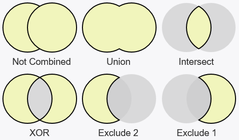
CombineParameters:ShapeN | ...-
Combine is a special shape type, that combines or merges two or more existing closed shapes in the meter, replacing them with a new "combined" shape. The first shape in the Combine definition will be the "parent", and any shapes, separated with the pipe
|character, with which it is combined are "children". This distinction is important in the context of how modifiers are inherited or not on combined shapes.Parameters:
ParentShapeName | CombineType ChildShapeName | CombineType ChildShapeName...Combine types:
Union: Merges the parent and defined child shapes together in the new shape.Intersect: Only the overlapping / intersecting portions of the parent and defined child shapes are drawn in the new shape.XOR: Only the NON overlapping / intersecting portions of the parent and defined child shapes are drawn in the new shape.Exclude: Only the portion of the parent shape that is NON overlapping / intersecting with the defined child shape is drawn in the new shape.
Examples:
Shape4=Combine Shape | Union Shape2 | XOR Shape3
Shape4=Combine Shape2 | Intersect Shape
Shape4=Combine Shape | Union Shape3 | Exclude Shape2Notes on Combine:
When shapes are combined, the parent shape's Attribute Modifiers, e.g. Fill and StrokeWidth, are automatically inherited by the new combined shape. Any Attribute modifiers on child shapes or the new combined shape are ignored.
When shapes are combined, all Transform Modifiers, e.g. Rotate and Scale, on both the parent and child shapes are performed first, before the combine is done. So for instance, a child shape can be rotated, and them combined with a parent shape. The new combined shape can then also have its own Transform Modifiers, which will be done after the shapes are combined.
The order of the front-to-back position of the shapes can be impacted by combining shapes, as the shapes are drawn in the numerical order of their ShapeN option name. Since the new combined shape is also a numbered shape option, some thought should be given when numbering combined and uncombined shapes, to get the order you want.
A Combined shape is always closed. Any open shapes or paths used as a parent or child will automatically be closed before they are combined.
Attribute Modifiers
FillDefault:Color 255,255,255,255-
Method used to fill a closed shape. This will be a keyword defining the type of fill, followed by any required and optional parameters for the type.
Fill Types:
Color: Fills the shape with a single required Color. The alpha value of the color code can be used to control the opacity of the shape.
Example:Shape=Rectangle 0,0,100,100 | Fill Color 255,0,0,255LinearGradient: Fills the shape with a linear color gradient. This consists of an angle in degrees, followed by a pipe|character and two or more sets of color ; percentage defining the gradient "stops".
Example: See Defining Gradients for details and examples.RadialGradient: Fills the shape with a radial color gradient. This consists of a definition of the gradient coordinates, followed by a pipe|character and two or more sets of color ; percentage defining the gradient "stops".
Example: See Defining Gradients for details and examples.
StrokeDefault:Color 0,0,0,255-
Method used to draw the stroke on a shape. This will be a keyword defining the type, followed by any required and optional parameters for the type.
Stroke Types:
Color: Draws the stroke with a single required Color. The alpha value of the color code can be used to control the opacity of the stroke.
Example:Shape=Rectangle 0,0,100,100 | StrokeWidth 4 | Stroke Color 255,0,0,255LinearGradient: Draws the stroke with a linear color gradient. This consists of an angle in degrees, followed by a pipe|character and two or more sets of color ; percentage defining the gradient "stops".
Example: See Defining Gradients for details and examples.RadialGradient: Draws the stroke with a radial color gradient. This consists of a definition of the gradient coordinates, followed by a pipe|character and two or more sets of color ; percentage defining the gradient "stops".
Example: See Defining Gradients for details and examples.
StrokeWidthDefault:1-
Size in pixels of the drawing stroke on the shape.
Example:
Shape=Rectangle 2,2,100,50 | StrokeWidth 4Notes on StrokeWidth:
This is not a "border around" the shape. It is the shape's "drawing stroke". One half of the stroke will be "inside" the shape, and one half will be "outside" the shape. With an odd-numbered StrokeWidth, which can't be divided evenly by two, the very most inside and very most outside pixels will actually be 1/2 pixels in size, with Direct2D "aliasing" the edge of the two pixels, to create "half pixels" and keep the stroke the correct size.
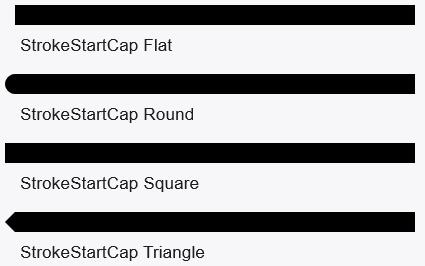
If you have a meter at the left or top of the skin, and define a shape with an X or Y of 0, that is where the shape will be drawn. However, since any StrokeWidth added to the shape will have one half of it outside the shape, you will need to move either the meter or the shape right or down to accommodate this, or part of the stroke will be outside the skin and truncated. StrokeStartCapDefault:Flat-
Defines the shape of a cap used at the start of the drawing stroke on an open shape. This modifier is ignored on closed shapes.
Cap Types:
Flat: This really no end cap, the same as leaving the modifier off entirely.Round:Square:Triangle:
Example:
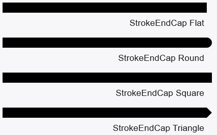
Shape=Rectangle 0,0,100,100 | StrokeWidth 4 | StrokeStartCap Round StrokeEndCapDefault:Flat-
Defines the shape of a cap used at the end of the drawing stroke on an open shape. This modifier is ignored on closed shapes.
Cap Types:
Flat: This really no end cap, the same as leaving the modifier off entirely.Round:Square:Triangle:
Example:
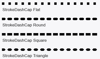
Shape=Rectangle 0,0,100,100 | StrokeWidth 4 | StrokeEndCap Triangle StrokeDashCapDefault:Flat-
Defines the shape of a cap used at the start and end of each dash in the drawing stroke defined by the StrokeDashes modifier.
Cap Types:
Flat: This really no end cap, the same as leaving the modifier off entirely.Round:Square:Triangle:
Example:
Shape=Rectangle 0,0,100,100 | StrokeWidth 4 | StrokeDashes 2,2 | StrokeDashCap Round StrokeDashes-
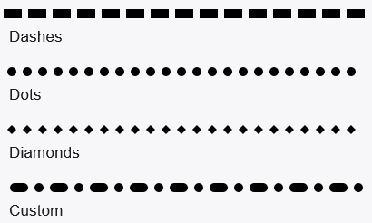
Defines a repeating dash or dot pattern for the shape's drawing stroke.
This is done with a single or repeating sets of comma-separated pairs of
▶ Show DashesDashSize,GapSize. These are not numbers of pixels, but are a multiplication factor based on the StrokeWidth. So2, 1.5would be a dash twice as long as the StrokeWidth, followed by a gap one and one-half times as long as the StrokeWidth, and this would be repeated for the entire stroke. This can be extended, i.e2,1,3,1.5,4,2to create a repeating custom dashed stroke of various sizes and gaps.
Example:
Shape=Rectangle 0,0,100,100 | StrokeWidth 4 | StrokeDashes 2,1.5Notes on StrokeDashes:
Dots instead of dashes are created in conjunction with the StrokeDashCap option above. If you specify a dash size of0, and a StrokeDashCap ofRoundyou will get dots,Triangleyou will get diamonds, and so on. So for instance0,2with a StrokeDaskCap ofRoundwill create NO "dash", just the two rounded end caps next to each other followed by a gap, which will create a dotted line. StrokeLineJoinDefault:Miter, 10.0-
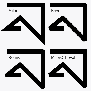
Defines the type of join used on angled connections of drawing stroke segments in a shape or path. An optional MiterLimit can be used to specify how sharp Miter joins are allowed to be (default is 10.0).
Join Types:
Miter: Mitered corners. The corner will be mitered up to the point of MiterLimit, then squared off.Bevel: Beveled or squared corners.Round: Rounded corners.MiterOrBevel: Miter is used unless the default or defined value of MiterLimit would be exceeded, in which case Bevel is used.
Miter or MeterOrBevel can be followed by a "," and an optional value for MiterLimit. Think of MiterLimit as controlling the amount of "pointiness" when a very sharp angle join is mitered. MiterLimit is a positive number greater than or equal to 1.0 that describes the limit as a ratio of the miter length to half the stroke's thickness.
Example:
Shape=Rectangle 0,0,100,100 | StrokeWidth 4 | StrokeLineJoin Bevel StrokeDashOffsetDefault:0-
Defines an offset where the first dash will start relative to the start of the shape. These are not numbers of pixels, but are a multiplication factor based on the StrokeWidth. So 0.0 would be none, 0.5 would be half the value of the SrokeWidth and 1.5 would be one and a half the value of the StrokeWidth
Example:
Shape=Rectangle 0,0,100,100 | StrokeWidth 4 | StrokeDashes 2,2 | StrokeDashOffset 1.0 RotateDefault:0, AnchorX, AnchorY-
Rotates the shape some number of positive or negative degrees of angle, either around the center of the shape (default), or optional X,Y anchor points in pixels relative to the top left of the shape.
Examples:
Shape=Rectangle 0,0,100,100 | Rotate 45
Shape=Rectangle 0,0,100,100 | Rotate 90,10,50 ScaleDefault:1.0, 1.0, AnchorX, AnchorY-
Scales the shape in the X and / or Y axis, using multiplication factors. Reducing the scale would be done with a scaling factor less than 1. The scaling is done either from the center of the shape (default), or optional X,Y anchor points in pixels relative to the top left of the shape.
Examples:
Shape=Rectangle 0,0,100,100 | Scale 1.5,0
Shape=Rectangle 0,0,100,100 | Scale 3.0,0.5,100,100Notes on Scale:
The size of any StrokeWidth, the drawing stroke, is not effected by scaling the shape. If you specify a StrokeWidth of 4, it will remain 4 pixels in size no matter how you scale the shape.A shape may be "flipped" or "mirrored" using Scale, by simply scaling it
-1.0on the axis you wish to flip. So Horizontal would be-1.0,1.0, Vertical would be1.0,-1.0, and Both would be-1.0,-1.0. SkewDefault:0.0, 0.0, AnchorX, AnchorY-
Skews the shape in the X and / or Y axis, some number of positive or negative degrees of angle. The skew is done either from the center of the shape (default), or optional X,Y anchor points in pixels relative to the top left of the shape.
Examples:
Shape=Rectangle 0,0,100,100 | Skew 20,0
Shape=Rectangle 0,0,100,100 | Skew 0,-20,100,0 OffsetDefault:0, 0-
Offsets (moves) the shape in the X and / or Y axis some number of positive or negative pixels.
Example:
Shape=Rectangle 0,0,100,100 | Offset 10,0 TransformOrderDefault:Rotate, Scale, Skew, Offset-
Allows you to change the default order in which the various Transform modifiers are applied. This can be important when anchor points are used in transforms, as for instance you may want to Scale before you Rotate. Any missing Transform modifier names will be placed to the back of the queue in the default order.
Example:
Shape=Rectangle 0,0,100,100 | TransformOrder Scale,Rotate
In this example the resulting order would be Scale,Rotate,Skew,Offset Extend-
A special modifier that will allow you to move Attribute and / or Transform modifiers from the ShapeN option to one or more named options in the meter. The intent of this is two-fold. First, to allow different shape to share modifiers without having to specify them repeatedly in each shape option. Second, to provide a way to shorten the overall length of the shape option line, by breaking out modifiers as desired to separate named options.
Example:
[MeterShapes]
Meter=Shape
Shape=Rectangle 0,0,100,50 | Extend MySharedModifiers, MyRotateAndScale1
Shape2=Rectangle 20,10,50,50 | Extend MySharedModifiers, MyRotateAndScale2
MySharedModifiers=Fill Color 0,0,0,255 | StrokeWidth 4 | Stroke Color 255,255,255,255
MyRotateAndScale1=Rotate 20 | Scale 1.5,0
MyRotateAndScale2=Rotate 45 | Scale 2.0,1.5
Notes on Extend:
The named options can be any names you like, however as with any other option in a .ini file, they must be unique to the [Section].
This functionality cannot "cascade". You can't have a named Extend option use an Extend modifier.
The modifiers in the named option are in effect "inserted" in the ShapeN option line where the Extend keyword is located. In the case of any duplication of a modifier this inadvertently causes, the rule is "last wins". If there are two instances of for example StrokeWidth that end up being defined for a single ShapeN option, the last one that is defined after all Extend named options are "inserted" will be performed.
Transform Modifiers
Extend Modifier
Defining Gradients
Gradients must be defined in a separate named option, which you then reference in Fill or Stroke modifiers on the shape. There are two kinds of gradients possible, LinearGradient and RadialGradient.
Examples:
[MeterShape] |
LinearGradientParameters:Angle | Color ; Percentage | ...-
This takes the form of the Angle for the gradient in degrees, a | pipe character, then a series of Color codes, a ; semi-colon, and a Percentage from 0.0 to 1.0 to define the position of the color in the gradient. Each series of Color ; Percentage are separated by a | pipe character.
Example:
[MeterShape]
Meter=Shape
Shape=Rectangle 1,1,101,101 | Fill LinearGradient MyFillGradient
MyFillGradient=180 | 255,0,0,255 ; 0.0 | 0,255,0,255 ; 0.5 | 0,0,255,255 ; 1.0
That will define a gradient at 180 degrees. It will start with a color of 255,0,0,255 (red) at percentage 0.0 (the start), will transition to a color of 0,255,0,255 (green) at percentage 0.5 (50 percent), and to 0,0,255,255 (blue) at percentage 1.0 (100 percent).
The Angle is defined as any number of degrees, with 0 or 360 starting directly to the right and rotating clockwise. This results in the following gradient directions on the Shape or Stroke:
- 0 (360) : Right to Left
- 90 : Bottom to Top
- 180 : Left to Right
- 270 : Top to Bottom
Note: Any defined color with a percentage outside the 0.0 to 1.0 range will not directly be displayed, but will still affect the interpolation of the gradient.
RadialGradientParameters: (See below)-
This takes the form of the required
CenterX, CenterYand any optional coordinate parameters, a | pipe character, then a series of Color codes, a ; semi-colon, and a Percentage from 0.0 to 1.0 to define the position of the color in the gradient. Each series of Color ; Percentage are separated by a | pipe character.Parameters:
CenterX, CenterY, OffsetX, OffsetY, RadiusX, RadiusY | Color ; Percentage | ...CenterX(required): Amount of pixels along the x-axis from the center of the shape to offset the center of the gradient ellipse.CenterY(required): Amount of pixels along the y-axis from the center of the shape to offset the center of the gradient ellipse.OffsetX(optional): Amount of pixels along the x-axis to offset the gradient origin relative to the gradient ellipse's center (CenterX).OffsetY(optional): Amount of pixels along the y-axis to offset the gradient origin relative to the gradient ellipse's center (CenterY).RadiusX(optional): The radius along the x-axis of the gradient ellipse.RadiusY(optional): The radius along the y-axis of the gradient ellipse.Color ; Percentage(required): 1 or more color and percentage pairs (separated by a semi-colon;) that defines the colors at specific percentages in the gradient.
Examples:
[MeterShape]
Meter=Shape
Shape=Ellipse 50,50,50 | StrokeWidth 0 | Fill RadialGradient MyGradient1
MyGradient1=0,0 | 155,200,232,255 ; 0.0 | 6,46,75,255 ; 1.0
Shape2=Ellipse 170,50,50 | StrokeWidth 0 | Fill RadialGradient MyGradient2
MyGradient2=0,0,20,20 | 155,200,232,255 ; 0.0 | 6,46,75,255 ; 1.0
Note: Any defined color with a percentage outside the 0.0 to 1.0 range will not directly be displayed, but will still affect the interpolation of the gradient.
Note on Gradients:
An alternative form of the gradients can be used by adding a "1" to the end of LinearGradient or RadialGradient These LinearGradient1 and RadialGradient1 forms use all the same setting values, but interpolate the gradient using an alternative method of handling gamma correction. In some cases you may find this makes for a smoother or brighter gradient transition.
Mouse Detection on Shapes
The behavior of Mouse Actions, for actions like LeftMouseUpAction, MouseOverAction, MouseScrollDownAction and the others is a bit different on a Shape meter than other meters.
In a Shape meter, the mouse is only detected on any solid part of the drawing created by any and all shapes in the meter. It is not dependent on any rectangular meter container. The mouse will instead be detected on any solid pixel created by the actual shape objects being drawn.
The mouse will be detected on any solid part of the shapes even if the shapes extend outside the boundaries of the meter container. This will be common with this meter type and is why we have changed the "target" of the mouse detection from the meter to the shapes. Quite often, there will be no W and H defined on the meter, and thus no meter container at all.
As always, there can only be one of each kind of mouse action in a [Section]. This means that you can't for instance have two ShapeN shapes in the meter, and have a distinct LeftMouseUpAction on each. In order to have distinct mouse actions of the same type on individual shapes, you will need to create the shapes in different Shape meters.
Device Independent Pixels
The values for pixels that are used in the Shape meter are Device Independent Pixels, and thus may be fractional. You may use 10.25 pixels or even 0.754 pixels when defining a shape. This is important for precision. However, this is only for the values used in shapes. The values used for meters, the W and H and X and Y of a Rainmeter meter, are still as of this writing in full integer pixels.
Examples
While the code here is for a simple skin that demonstrates various ways to manipulate the Rectangle shape type, the .rmskin in the Download button is a much more robust suite of skins demonstrating many of the aspects of the Shape meter.
[Rainmeter] |
An example skin demonstrating the Shape meter.