AudioLevel plugin
Plugin=AudioLevel monitors and analyzes streams of audio sound to or from an audio endpoint.
AudioLevel will monitor, filter and analyze the amplitude (volume level) of sound input or output on the default or defined device and channels. The value returned will be a number from 0.0 to 1.0, which will be treated as a percentage for use in meters.
This can be used to create a volume level VU Meter for defined channels, or optionally can filter the audio stream into distinct frequency bands to create a Spectrum Analyzer.
The plugin monitors the amplitude of the post-mixer signal at a Windows audio endpoint. (i.e. sound card speaker output, USB audio interface, headphone port, microphone input) It does this by creating a WASAPI capture client in loopback mode. The capture client streams audio data to the plugin where it can be filtered and measured. The resulting volume level is returned by the plugin for use in Rainmeter measures and meters.
Note: Creating meters that display sound levels in real-time will require that the skin be set with a fairly low Update rate in the [Rainmeter] section of the skin. While the plugin is quite resource friendly and efficient, some care should be taken when deciding how much analysis should be done on the signal, and it is recommended that this plugin be used in a skin dedicated to it, and not as a part of a larger skin where the low update rate may cause higher CPU usage.
Usage
AudioLevel operates with a "parent / child" approach. A single "parent" AudioLevel measure is used to obtain and analyze the audio stream, and then as many "child" measures as desired request data from the parent to get individual values to display in meters. Example:
; This parent measure processes the default audio output. |
Note: Only the Type, Channel, FFTIdx and BandIdx child measure options can be changed dynamically with !SetVariable or !SetOption. Parent measure options may not be changed dynamically.
Options
- General measure options
-
All general measure options are valid.
Parent measure options
PortDefault:Output-
Specifies whether you want to measure the input or output levels for the given device.
Output(default)Input
IDDefault:None-
Specifies the audio device to measure.
If not set, it will use the default device for the specified Port. If you specify
Port=Outputand noID, the plugin will connect to the default audio output device defined in Windows.To specify a device other than the default, you will need to find the Windows device ID. See the
DeviceListchild measure option for more info.Device IDs will be in the form:
{0.0.0.00000000}.{5c106e65-26b4-4d05-a9bf-b207a71e9eaa}Note: The default audio device in Windows can be changed by using "Manage Audio Devices" from the Windows Start menu.
RMSAttackDefault:300-
Specifies the time in milliseconds over which to interpolate as the signal level increases. For example, how quickly a needle jumps up as the sound level increases.
RMSDecayDefault:300-
Specifies the time in milliseconds over which to interpolate as the signal level decreases. For example, how quickly a needle subsides as the sound level decreases.
RMSGainDefault:1.0-
A multiplication factor that will be applied to the RMS analysis.
PeakAttackDefault:50-
Specifies the time in milliseconds over which to interpolate as the signal level increases. For example, how quickly a needle jumps up for a higher peak.
PeakDecayDefault:2500-
Specifies the time in milliseconds over which to interpolate as the signal level decreases. For example, how quickly a needle subsides to a lower peak.
PeakGainDefault:1.0-
A multiplication factor that will be applied to the Peak analysis.
FFTSizeDefault:0-
A number value for the frequency resolution of the output data.
This will be an even integer greater than or equal to 0, usually a power of 2. Typical values are 256, 512, or 1024, with the higher the number the greater the frequency resolution.
Note: It should be kept in mind that as this number increases, more CPU resources and time will be needed to analyze the audio stream. A very high number here can both impact CPU usage and potentially cause some "lag" between the sound generation and the measurement by the plugin.
FFTOverlapDefault:0-
Optionally, the FFT can be windowed to overlap successive sections. A Hann function is used to shape the data before the FFT is applied. Typical values are half the FFTSize. Increasing this value will lower the latency between the audio and the measure's response, at the cost of extra CPU.
FFTAttackDefault:300-
Specifies the time in milliseconds over which to interpolate as the signal level increases. For example, how quickly a needle jumps up for a higher level.
FFTDecayDefault:300-
Specifies the time in milliseconds over which to interpolate as the signal level decreases. For example, how quickly a needle subsides to a lower level.
BandsDefault:0-
An integer, specifying the number of frequency bands to generate.
The FFT data can be extrapolated into a number of log-spaced frequency bands, similar to a typical spectrum analyzer. This option specifies the number of bands to create.
FreqMinDefault:20-
A number in Hz, specifying the minimum frequency band calculation.
FreqMaxDefault:20000-
A number in Hz, specifying the maximum frequency band calculation.
SensitivityDefault:35.0-
A number specifying in what dB range the measure will return
FFTandBanddata. Increasing this value will cause the measure to respond to quieter sounds, decreasing it will only trigger the measure on louder sounds.
RMS options
RMS is a way of calculating the average of values over a period of time, using the mathematical algorithm Root Mean Square. The signal value (amplitude) is squared, averaged over a period of time, then the square root of the result is calculated. The result is a value, that when squared, is related (proportional) to the effective power of the signal.
This is the most meaningful way of measuring audio volume levels in a skin.
Note: To disable all RMS filtering, set both RMSAttack and RMSDecay to 0, and RMSGain as the default 1.0.
The following parent options are used in combination with child measures having the Type=RMS option set.
Peak options
Peak options are similar to RMS options, but measure the peak (high) values rather than squaring to obtain an average over a period of time.
Note: To disable all Peak filtering, set both PeakAttack and PeakDecay to 0, and PeakGain as the default 1.0.
The following parent options are used in combination with child measures having the Type=Peak option set.
FFT options
FFT options transform the signal from the time domain to the frequency domain, with FTTSize determining how many points you get back in the frequency domain. This is done by analyzing the audio stream into a linear-based number of points using the mathematical algorithm Fast Fourier Transform.
This frequency information can then optionally be extrapolated into logarithm-based Bands to distinctly measure by frequency in the ranges that are the most useful for spectrum display, based on the way humans detect changes in sound.
In order to use Bands, both FFTSize and Bands must be set on the parent measure.
The following parent options are used in combination with child measures having the Type=FFTand FFTIdx or Type=Band and BandIdx options set.
Child measure options
ParentRequired-
Defines the parent AudioLevel plugin measure to read values from.
Example:
Parent=SomeMeasureName ChannelDefault:Sum-
This specifies which audio channel level to read from the parent. Channels can be identified by name or number, e.g.
Channel=0is the same asChannel=LorChannel=FL.LorFLor0RorFRor1Cor2LFEorSubor3BLor4BRor5SLor6SRor7SumorAvg
TypeRequired-
Specifies the type of data to retrieve from the parent measure.
RMS: The current RMS level (0.0 to 1.0) corresponding to the specifiedChannel.Peak: The current Peak level (0.0 to 1.0) corresponding to the specifiedChannel.FFT: The current FFT level (0.0 to 1.0) corresponding to the specifiedFFTIdxoption.FFTFreq: The frequency in Hz corresponding to the specifiedFFTIdxoption.Band: The current FFT level (0.0 to 1.0) value corresponding to the specifiedBandIdxoption.BandFreq: The frequency in Hz corresponding to the specifiedBandIdxoption.Format: A string describing the audio format of the device connected to with the parentIDoption.DeviceStatus: Status (0 or 1) of the device connected to with the parentIDoption.DeviceName: A string with the name of the device connected to with the parentIDoption.DeviceID: A string with the Windows ID of the device connected to with the parentIDoption.DeviceList: A string with a list of all available device IDs for the specifiedPortThis can be used to identify a desired device ID for use in the parentIDoption.
Example:
Type=RMS FFTIdxDefault:0-
Specifies which FFT point you want to extract from the parent.
FFTSizemust be enabled on the parent measure to use this option.Valid values range from 0 to (FFTSize/2).
BandIdxDefault:0-
Specifies which frequency band number, starting with 0, you want to extract from the parent.
FFTSizeandBandsmust be enabled on the parent measure to use this option.Valid values range from 0 to (Bands-1).
Examples
[Rainmeter] |
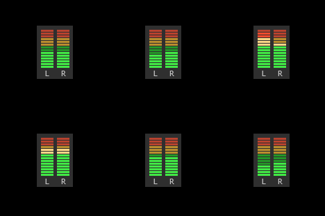
Simple Left/Right volume levels using RMS and Bitmap meters:

[Rainmeter] |
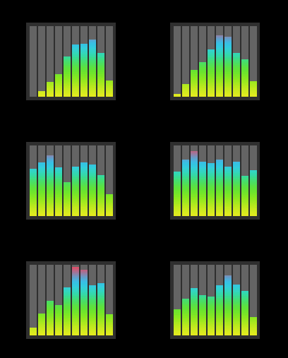
Simple spectrum visualization using FFT/Bands and Bar meters:
